Aaron_Harrow


Curved screen projection with Isadora


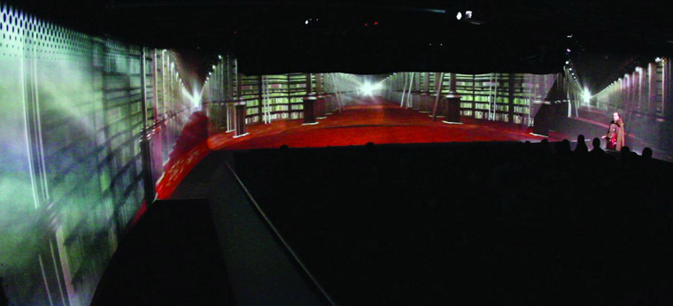
The recent show Spy Garbo involved projection on a 140' long x 13' high curved projection screen, using 9 edge-blended projectors to achieve a seamless image. Since projecting onto a curved surface produces distortion, it was necessary to come up with a way to correct this and make the image appear flat.

Jeff Morey and I had already dealt with a similar situation in our work on the American Woman exhibition at The Metropolitan Museum of Art - in which we projected 360 degrees, floor to ceiling in an oval room.

Spy Garbo scenic design (Neal Wilkinson)

We experimented with many methods to pre-distort the content to compensate for the curved walls (settling on using 3D Studio Max), but even though we were only dealing with a single 4 minute animation, the pre-distortion process for a 6 projector blend was extremely time consuming, and had to be re-rendered every time content changes were made.

Pre-distorted 6-projector output for American Woman at The Met

Spy Garbo on the other hand was a full-length play with at least 80 minutes of video content so it was clear from the start that we had to find a better solution. At the time of The Met project, Isadora (our software of choice for both pieces) did not have a way of applying curved distortion in real time, but all that changed with v1.3 and the 3D Mesh Projector actor.
I should state off the bat that I adopted a very experimental DIY approach to this problem, and although the results were excellent, there are certainly many things I could have/should have done differently...use this approach at your own risk!

1. The Grid

Before any of the fun stuff could happen, we had to establish a physical grid on the screen surface. This would enable us to get an accurate visual representation of the screen curvature. It was painstaking work - placing drfting dots at 1 foot intervals across the entire surface of the screen! Took 3 of us the best part of 3 days.

Jeff, Magnus and lots of Alvin drafting dots!

We then traced the portion of the grid-points 'visible' to each of the 9 projectors, resulting in 9 grids. We did the tracing using Photoshop in full-screen mode.

2. Tracing the traced grids

Isadora's 3D Mesh Projector actor works by using an external data file to describe the distortion. It is essentially a text file containing a series of coordinates, and it is based on the work of Paul Bourke, Associate Professor at the University of Western Australia and general projection geometry guru. My mission became figuring out how to translate the bitmap-versions of the grids into X/Y coordinates which could be read by the Mesh Projector actor. After exploring many different options, I finally hit upon a useful little app called GetData, which is essentially a way of manually digitizing graphs and grids and outputting the results as numbers. A fair amount of manual mouse-labor resulted in a bunch of X/Y data for each of the 9 sections of the screen.

GetData screenshot


3. Deciphering the data file

Here's what a portion of the .data file looks like:

1
18 13
-1.098729 -0.856584 0 0 1
-0.921473 -0.838331 0.05883 0 1
-0.746823 -0.827901 0.11766 0 1
-0.572173 -0.812256 0.17649 0 1
-0.40013 -0.799218 0.23532 0 1
-0.256761 -0.791395 0.29415 0 1
-0.115999 -0.77575 0.35298 0 1

When it came to producing a correctly formatted data file, I trawled Paul Bourke's website for some insight into how things worked, and sure enough he explains that these numbers correspond to:

1
(type of map)
- - - -
18
(grid width)
13
(grid height)
- - -
-1.098729
(X coordinate)
-0.856584
(Y coordinate)
0
(U value)

0
(V value)

1
(intensity)


A key concept in this process is XY coordinates versus UV coordinates. It took a charitable Mr Bourke to explain this to me...hopefully he won't mind me quoting him here:


"The coordinates you are measuring from the projector perspective correspond to the (x,y) coordinates of the mesh you want. If you are measuring these in pixels then for the mesh .data file you need to scale them to +- vertically and -aspect to aspect horizontally, this is known as normalised screen coordinates.
x = 2 * (width/height) * (xpixel - width/2) / width
y = 2 * (ypixel - height/2) / height.
The (u,v) coordinates come from the grid you have marked out on the surface being projected onto, range from 0 to 1."


So we can think of XY as being 'screen' coordinates and UV as being 'real world' coordinates. Or at least that how I think of it.

More details on this can be found on Paul Bourke's site.


4. Excel to the rescue

The next step was finding a way to automate the calculation of normalised screen coordinates and UV coordinates and then wrap it all up in a nice space separated text file. Of course this is what Excel excels in (sorry...) so I created a spreadsheet to do the heavy lifting.
Even so this process turned out to be extremely time-consuming as I had to tweak and experiment to get the results I needed. I also found that I had to revisit the original grids and add more rows/columns in some cases.
If you look at the screenshot here, you can see that columns B and C contain the raw XY data from my traced grids, measured in pixels.

Excel spreadsheet screenshot

Columns E-I contain the actual data that is exported and consist of the normalised screen coordinates (XY data with the above formulae applied) and the UV 'texture' coordinates.
It was these UV coordinates that gave me the most trouble. I assumed that the values would range evenly from 0-1 according to the resolution of the grid, and in some cases this seemed to be true. In others however (e.g. the V values here) I found I had to tweak the range in order to produce the correct distortion. So columns K-S in this example are there to make my hit-and-miss tweaking process a little easier!

To my chagrin, I later figured out that I had missed a vital and obvious detail: the horizontal coordinates should be -ASPECT to ASPECT (as Mr Bourke had originally stated), not 0-1 as I mistakenly assumed.
3/4 = 0.75, which is what my maximum V value ended up, albeit more through experimentation than mathematics!

The other thing to note is that the values are arranged vertically in groups of 18 (the number of columns in my original grid) and there are 13 of these groups stacked on top of each other (the number of rows in my grid). You can see the grey/white alterating pattern in the screenshot.

It is extremely important that these numbers match exactly the numbers in the 2nd line of the .data file (18 3) otherwise nothing will work!
So all that's left here is to export the relevant numbers (in this example columns E-I to a space separated text file, then change it's extension to .data - which is the file type that Isadora's Mesh Projector will be looking for.


5. Isadora at last!


OK so here's the moment we've been waiting for! Fire up Isadora and drag a Movie Player and a 3D Mesh Projector on to the stage.
The 3D Mesh Projector is actually very straightforward to use, although there are a couple of quirks.
If you click the screenshot you can see that I have had to add a Flip actor (vertical), and also I have set the Y-Rotation of the 3D Mesh Projector actor to 180.

Isadora screenshot

Whether this is a bug, or the result of some flaw in my methodology I don't know, but this is what ended up working for me. I also tweaked the Image Scale, Shift Horizontal and Shift Vertical values once I got into the space.
One other quirk (for me at least) is that the actor automatically tiles your input movie as you alter the Shift values. In our case this was not what we wanted since we were edge-blending 9 projectors. It would be nice if it there were an option to turn tiling off, but it's not a major problem either way.
In theory you can build edge-blends directly in the 3D Mesh Projector by altering the Intensity values in the .data file (the last value on each line) but it seemed too limiting and fiddly for me. I tried it out just to confirm that it worked.

Lastly, I haven't covered the process by which we divided up the content to fit exactly into each of the 9 projection areas. Briefly put, we created a giant After Effects composition at our full resolution of 8060x768 (derived from the aspect ratio of the actual screen) then nested it inside 9 individual 1024x768 comps. We then nudged and scaled each one to compensate for variations in projector positions. The resulting After Effects composition became our template, and all we had to do in order to chop up our content into perfectly scaled and aligned sections, was to set up output module presets, drop our content into the master composition and hit render.

After Effects screenshot


So there you have it - easy ;) Hopefully this will prove useful to someone sometime. I doubt that this arduous process will be necessary for much longer as I imagine a simple GUI for the 3D Mesh Projector actor will be developed soon, fingers crossed!

Here's a shot from the final show:

Spy Garbo library scene